
Roof & Wall Ventilation Construction Details
From 1 July 2026, updated National Construction Code (NCC2025) provisions bring in stricter condensation management requirements for wall and roof cavities under part 10.8 of the Housing Provision - Condensation Management. This is part of a broader push for healthier more durable homes. This page answers the questions builders and designers ask most about drained and ventilated cavities, vapour-permeable membranes and roof space ventilation under the new provisions.
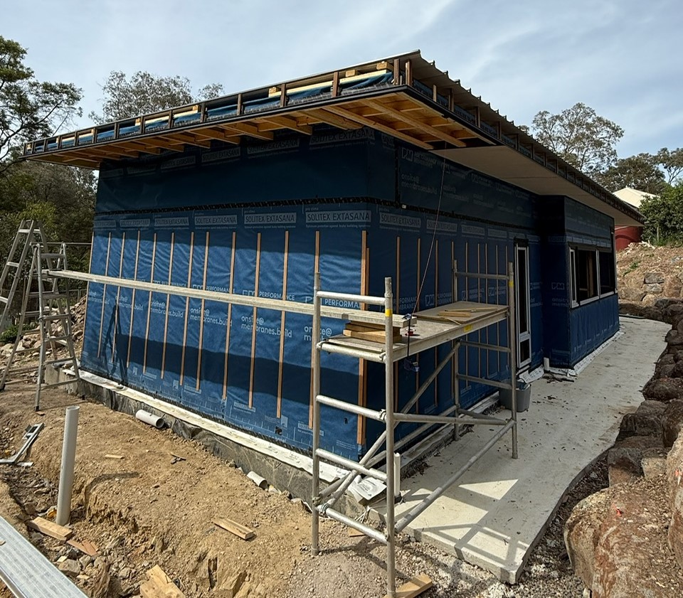
This guidance applies Australia-wide, however most of the specific ventilation and membrane examples on this page relate to climate zones 6, 7 and 8, where ventilation cavities are now mandatory for states adopting NCC2025 part 10.8. If you're building outside these zones, check that the membrane choice complies with current NCC requirements for your climate. See table in, "What are the changes in the code?" below for vapour permeance requirements. Also note, different states have different timelines for adoption of NCC2025. See table in, "Where are drained and ventilated wall cavities now mandatory?".
Frequently Asked Questions
What are the changes in the code?
NCC 2025, part 10.8 Condensation Management has some significant changes from the previous version of the code for condensation provision in wall and roof assemblies.
The main changes are:
- updated membrane class requirements by climate zone, and for the first time membrane requirements for Climate Zones 1-3 which previously have been unregulated
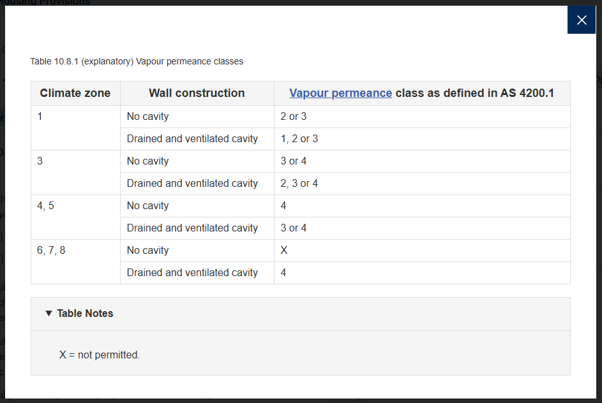
- the introduction of mandatory wall cavities in Climate Zones 6-8, and membrane requirements in other climate zones being dependent on whether a cavity is present in the wall assembly (see table below)
- roof ventilation pathway height and opening sizes, required in Climate Zones 6-8, have been updated from NCC 2022 and are now split into, "Ventilation of a roof space with the primary insulation layer not parallel to the roof plane," and, "Ventilation of a roof space with the primary insulation layer parallel to the roof plane."
NCC2025 Explanatory Table 10.8.1 shows the wall membrane requirements in different climate zones with and without cavities
Where are drained and ventilated wall cavities now mandatory?
Under NCC2025 drained and ventilated wall cavities are mandatory in climate zones 6, 7 and 8 behind external wall claddings.
They are also required in any climate zone where there is no exterior membrane between the insulation and external cladding.
Importantly there are some carve outs with ventilated cavities not being required for:
- a single skin masonry wall
- a single skin concrete wall
- a wall constructed from insulated sandwich panels for the full extent of the external wall
- a wall that does not form part of the building envelope
- any portion of the external wall below natural ground level
See NCC2025 Part 10.8.1 — External Wall Construction, for more details.
State Adoption:
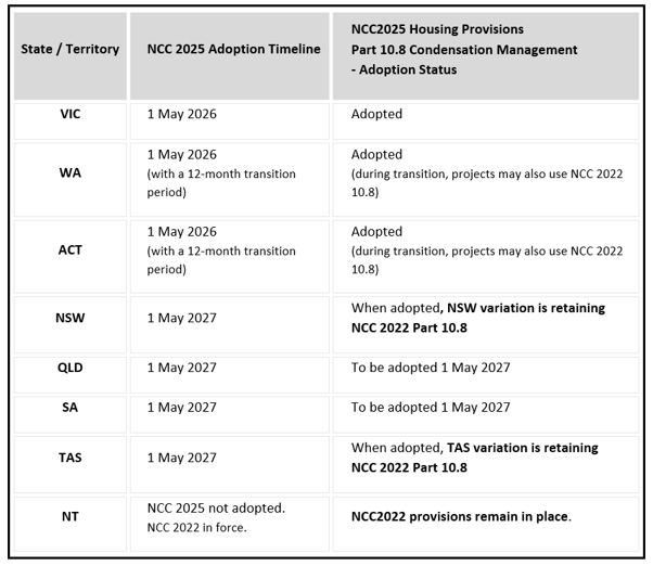
Different states have different schedules for the adoption of NCC2025, and some states are currently choosing not to incorporated part 10.8 Condensation changes at all, even when adopting the rest of NCC2025. Check the table below to see when your state is adopting NCC2025 and the new 10.8 Condensation Management Housing Provisions.
What are the minimum wall cavity construction requirements under NCC 2025 10.8 Condensation Management?
There are 4 core requirements under the 2025NCC code for wall cavity compliance:
- Cavity battens must be a minimum of 12mm.
- The cavity should be unobstructed by any control layer.
(This means that membranes need to be tight, or cavity battens increased in size to allow for sagging into the cavity.)
- There must be ventilation openings to the exterior at the top and bottom.
(Where a wall is separated by a roof structure - commonly found where a ground floor roof buts into an upper wall - each portion of wall needs a ventilation opening top and bottom.)
- The cavity must be drained to the exterior, with a free area of not less than 1,000mm²/m at the base and top of each cavity
(ie. a continuous 1mm cavity min.)
It should be noted that these requirements represent minimum standards under the code. Better stack effect ventilation and drying will be achieved by making openings and ventilation pathways larger, with many practitioners aiming for openings of the same cross-sectional area as the cavities for unimpeded flow.
How do cavities work?
Cavities form part of a home's moisture control strategy, and are comprehensively explained in the Performance Construction section of the SBA Roadmap to Net Zero Sustainable Homes.
The job of cavities is to give a convenient location for any moisture to condense and drain away, and to allow structures to dry out where there is condensation or water leaks within an assembly.
To understand the benefit ventilated cavities can provide to our homes, especially in the southern half of Australia, it is helpful to understand the natural mechanism at play...
Nature always seeks to balance pressure differences. Where there is more moisture in a volume of air (ie. higher vapour pressure) on one side of an assembly than the other there will be a vapour drive from the higher to the lower vapour pressure, and moisture will move through the assembly if the pore structure of the materials allow it, in that direction.
Another key principle to understand is that warmer air can hold considerably more molecules of water vapour in it than cold air. So vapour drive tends to move from warm moist air masses to cooler drier air masses.
In the south in Australia the warmer, moister airmass tends to be inside the home where occupants are typically heating to 20deg, and generating water vapour in the form of showering, washing and breathing into the internal air space. This creates an internal air mass with more moisture per volume of air than on the outside of the home, and water vapour therefore moves through the building from the inside to the outside.
In northern Australia it swaps around. The outside air mass can be hot and humid, having a high vapour loading per air volume (ie. a high vapour pressure), while inside homes are commonly airconditioned to 20deg and much drier, with the airconditioning removing moisture from the air via the condensate line. This situation creates higher vapour pressure on the outside and lower on the inside, so the vapour drive is from the outside to the inside.
Because atmospheric vapour pressure is dependent on temperature and moisture, it varies not only by climate, but also seasonally within many Australian climates, and can even change direction over the course of a day.
Below is a table showing seasonal vapour drive within our capital cities, and the dominant annual vapour drive of each capital city.

* Note: Canberra results are based on historical BOM Canberra City datasets rather than current Canberra Airport data (which was unavailable). The Canberra results should therefore be considered moderate confidence, whereas the other cities are based on current BOM datasets.
Because vapour drive direction can change in many climates, the general rule of thumb when choosing a membrane is to choose one "as breathable as you can and only as low permeability as you need". This is what NCC2025 explanatory table 10.8.1 tries to do.
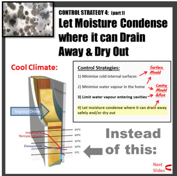
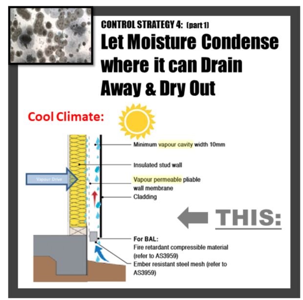
Let's look at an example of vapour drive in action using a wall structure in a cool climate (Eg. Melbourne).
(See the first diagram below.)
For most of the year the air inside the home is warmer and more moist than the outdoor air which is often cold, especially on winter evenings. The dominant drive is therefore from the inside to the outside.
As water vapour moves from the warm internal side towards the colder external side it cools down, and depending on the external temperature on the day, can often get to the point where the water vapour starts to condense out within the cavity. This can lead to dripping within the wall and wetting of the bottom plate. Over time, this mechanism can lead to premature rotting, and potentially mould growth within the cavity.
How ventilated cavities help to manage this effect
Example A - including a ventilated cavity and class 4 membrane in a light weight clad wall:
The diagram below shows a ventilated cavity with vapour permeable class 4 membrane on the outside of the insulation layer.
While it keeps out liquid water, the class 4 membrane has pore sizes that let water vapour easily pass through to either vent away, or condense within the cavity and drain away.
To aid the drying, a ventilation opening is provided at top and bottom of the cavity to allow stack ventilation to get going as the wall warms during the day.
Note, under NCC2025, the cavity width is now 12mm minumum, and a 1000mm2/m ventilation gap is required at top and bottom. This equates to a continuous 1mm gap. As noted previously however stack effect ventilation will be further improved if the dimensions of openings and cavity width are increased.
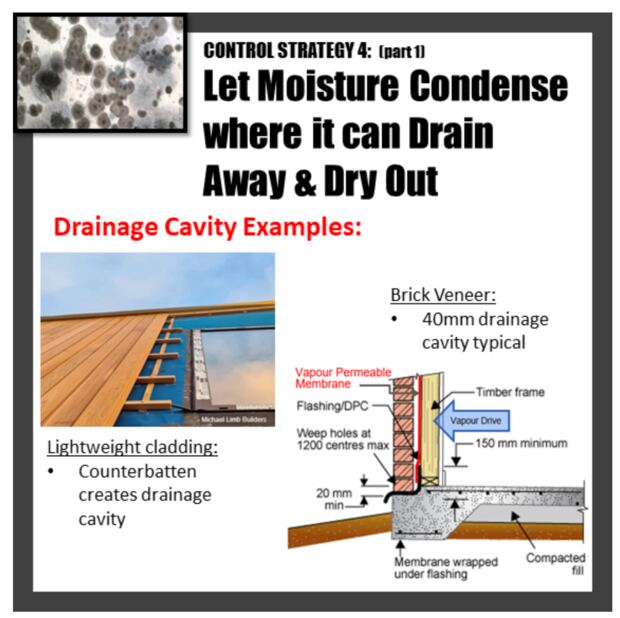
Example B - including a ventilated cavity and class 4 membrane in a brick veneer:
The diagram below shows brick a standard 40mm brick veneer cavity. Being >12mm this cavity complies with NCC2025. However, to achieve 1000mm2/m opening at the bottom, weepholes would have to be increased every 3rd brick. (Assuming weepholes are 10mm wide x 76mm standard brick tall.)
For more detailed explanation, head to the Performance Construction section of our Roadmap
For further examples and schematics see the end of this webpage.
What ventilation is required for roof spaces under the new provisions?
The NCC2025 requires roof ventilation for climate zones 6, 7 and 8.
This involves providing a permanent 18mm high ventilation cavity pathway immediately above the insulation, OR above a Class 4 membrane directly above the insulation, with openings at the top and bottom of the roof. The size of the openings vary with roof slope, m2 size, and roof configuration detailed below.
There are 2 broad configurations noted under the code, based on where the insulation layer sits in relation to the roof plane:
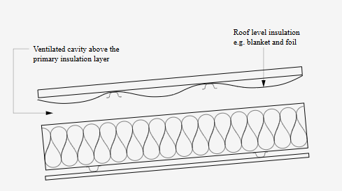
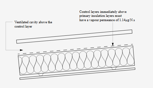
1. Insulation parallel to the roof plane:
This is referring to flat framed roof construction, and is illustrated in the code using the 2 following scenarios:
Eg. 1: Roof blanket or foil with the ventilation pathway over a primary insulation layer (NCC2025 Fig 10.8.4b)
Eg. 2: Ventilation pathway over a class 4 membrane directly above the insulation layer (NCC2025 Fig 10.8.4c)
There must also be a ventilation opening at the low and high side of each roof to facilitate the air movement. The opening requirement varies with roof pitch and roof size, with openings at the eave being bigger than those at the ridge to give ample air supply and minimise the potential risk of drawing air from internal spaces through fixture penetrations. The opening sizes for flat framed construction depend on roof size. The code stipulates:
- for roofs less than 10 m2, is ventilated to outdoor air through openings not less than—
- 7,000 mm2/m provided at the eaves or low level; and
- 5,000 mm2/m at the high level or ridge; and
- for all other roofs, is ventilated to outdoor air through openings not less than—
- 20,000 mm2/m provided at the eaves or low level; and
- 5,000 mm2/m at the high level or ridge.
For full details see NCC2025 10.8.4
2. Insulation not parallel to the roof plane:
This is referring to a roof with attic space and flat ceilings.
The following illustration from the code shows the standard setup:
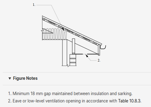
The ventilation opening for roofs with attics and flat ceilings depends both on roof size and roof pitch. Requirements are found in table 10.8.3
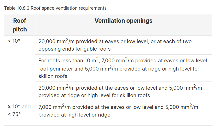
Note, for this roof configuration, high level openings may be either at the ridge or not more than 900 mm below the ridge or highest point of the roof space, measured vertically or 1/3 of the height of the roof below highest point of the roof, whichever is least.
For full details see NCC2025 10.8.3
Below is an example of combined roof type roof construction:

Note, NCC2025 allows some roof types to be exempt from ventilation requirements. They are:
- a concrete roof
- a roof made of insulated sandwich panels
- a roof subject to Bushfire Attack Level FZ requirements under AS 3959
- a tiled roof without a control layer located above the primary insulation layer.
(This is considered to already provide enough ventilation.)
What are the key compliance risks or common mistakes?
The following are some common risks when undertaking cavity ventilation, and are important to consider and mitigate against, especially when approaching cavity ventilation for the first time:
- Working to minimums
When working to minimums all it takes is membranes or roof blankets that sag, or unforeseen packing, etc., to narrow ventilation pathways & openings below minimum requirement. It is recommended to give some extra space beyond minimum when creating cavities and openings. - Drainage consideration when specifying a roof ventilation path above a membrane
The night sky is very cold. When an air gap is created under roof cladding, and temperatures and humidity is right, condensation will occur. If specifying a membrane under, pay particular attention to product installation manuals and creating a drainage plane that goes all the way to outside of the building. - Cavity closers to stop insects and vermin
Cavity closers are a very good idea to stop wildlife entry, but make sure that you know the opening percentage of any mesh or steel sheet used and make sure the size of the opening is increased to account for it, so that minimum ventilation opening requirements are maintained. See this section of the SBA Roadmap Step 3: Performance Construction. - Differing climate zone requirements
If building the same house design in different climates, make sure the membrane selection is updated to work with the particular climate, and remember climate zones 6-8 require wall & roof cavitity ventilation. - Suction from Internal Airmasses
When introducing roof ventilation in standard construction with numerous lights or other ceiling plaster penetration, there is a danger that roofs will draw makeup air from internal air masses. To counter this, limit fixture penetration in the external ceilings, or consider internal tightness membranes, with dropped plaster ceilings under to house recessed lighting. - Where the ventilation pathway passes through an attic roof space with flat-ceiling insulation, use raised-heel trusses with enough heel height that insulation has room to fully loft without blocking the required 18mm ventilation path at the wall edge.
Technical Library
Technical & Supplier Resources
Roof Changes to the Australian National Construction Code Ventilation (2025)
Proclima Construction Details Library

DCTECH Technical Library

An Australian Based Study On Airtightness and Moisture Management

Condensation in Buildings – Tasmanian Designers’ Guide - Version 2

Example Details & Additional Resources
(NOTE: These are examples only, and should be adapted where appropriate to your specific project by your professional team.)
NCC 2022 Above membrane Ventilation for Roof < 10 degree pitch
Above membrane roof ventilation - roof with insulation parallel to roof plane

Above membrane roof ventilation - trussed roof with insulation not parallel to roof plane

Above membrane ventilation with eave vent and drainage - roof with insulation parrallel to roof plane

Above membrane ventilation with no-eave-vent and drainage - roof with insulation parrallel to roof plane

Below roof blanket ventilation - roof with insulation parallel to roof plane

Ventilated wall cavity to insulated slab edge detail

Become part of the movement.
Join the Sustainable Builders Alliance and position yourself as a leader in high performance, healthy, low impact homes, Australia's fastest growing segment of residential construction.